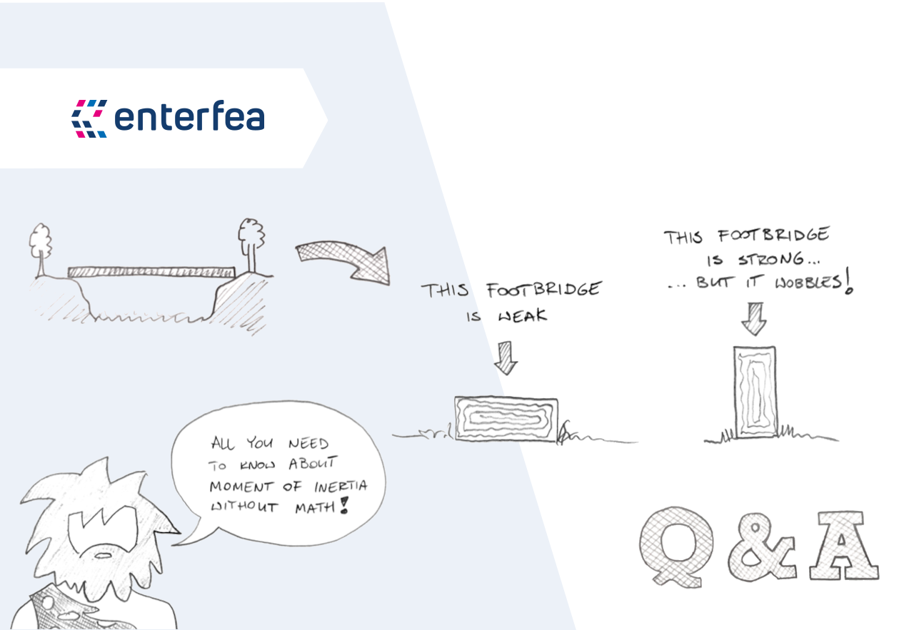
Okay, so the other day I needed to figure out the moment of inertia for a standard I-section beam. You know, those steel beams shaped like a capital ‘I’. It’s one of those things you need to know for figuring out how much a beam will bend under load. Not super complicated, but you gotta do it step-by-step.

Getting Started – The Beam Itself
First things first, I had to get the actual dimensions of the I-section I was working with. Grabbed my measuring tape and noted down:
- The total height of the whole thing. Let’s call it ‘H’.
- The width of the top flange (the top flat part). Let’s call it ‘B’.
- The thickness of that top flange, ‘tf’.
- The thickness of the web (the vertical middle part), ‘tw’.
- The width and thickness of the bottom flange. Usually, for standard I-beams, the bottom flange is identical to the top one, so same ‘B’ and ‘tf’. Made things a bit easier.
Got all those numbers written down nice and clear.
Breaking It Down
Now, the way I always tackle this is by thinking of the I-section as three simple rectangles stacked together:
- Rectangle 1: The top flange.
- Rectangle 2: The web (the tall skinny bit in the middle).
- Rectangle 3: The bottom flange.
The plan was simple: figure out the moment of inertia for each rectangle separately, and then add them all up. But there’s a catch – you can’t just add the simple inertia values. You need to add them up relative to the center of the entire I-section shape.
Finding the Center (Centroid)
Because my I-beam was symmetrical (top and bottom flanges were the same), finding the center was easy. The vertical center line is right down the middle of the web. The horizontal center line (which is what we usually care about for bending) is exactly halfway up the total height ‘H’. So, the centroid was at H/2 from the bottom edge. If the beam wasn’t symmetrical, I’d have had to do a bit more calculation involving the areas and individual centers of the rectangles, but thankfully, not this time.

Calculating for Each Piece
Alright, calculator time. For each rectangle, I needed two things:
- Its own moment of inertia about its own center line. For a rectangle, this is pretty standard: `(base height^3) / 12`. Remember ‘base’ and ‘height’ depend on which way you’re bending it! For bending the usual way (like a floor beam), the base is the width of the flange/web, and the height is its thickness/height.
- How far its center is from the overall center of the I-beam. Let’s call this distance ‘d’.
Top Flange:
- Its own inertia: `(B tf^3) / 12`. This value is usually pretty small because ‘tf’ (the thickness) is cubed.
- Its area: `A_top = B tf`.
- Distance ‘d’: Its center is at `H – tf/2` from the bottom. The overall center is at `H/2`. So the distance `d_top = (H – tf/2) – H/2 = H/2 – tf/2`.
- Total contribution from top flange: `(Its own inertia) + (A_top d_top^2)`. This second part, the `Ad^2` term, is usually much bigger because ‘d’ is squared.
Web:
- Its height is `h_web = H – 2tf`.
- Its own inertia: `(tw h_web^3) / 12`. This is often significant because `h_web` is cubed.
- Its area: `A_web = tw h_web`.
- Distance ‘d’: The web’s center is right at `H/2`, same as the overall center. So `d_web = 0`.
- Total contribution from web: `(Its own inertia) + (A_web 0^2) = (Its own inertia)`. Nice and simple.
Bottom Flange:
- It’s identical to the top flange because of symmetry.
- Its own inertia: `(B tf^3) / 12`.
- Its area: `A_bottom = B tf`.
- Distance ‘d’: Its center is at `tf/2` from the bottom. The overall center is at `H/2`. So the distance `d_bottom = H/2 – tf/2`. Same distance as the top flange, just in the opposite direction, but since we square it, it doesn’t matter.
- Total contribution from bottom flange: `(Its own inertia) + (A_bottom d_bottom^2)`.
Putting It All Together
Finally, I just added up the contributions from the three parts:

Total Moment of Inertia (Ix) = (Contribution from Top Flange) + (Contribution from Web) + (Contribution from Bottom Flange)
Since the top and bottom flanges were identical, it was basically:
Ix = 2 [ (B tf^3)/12 + (B tf) (H/2 – tf/2)^2 ] + [ (tw (H – 2tf)^3) / 12 ]
Punched all the numbers from my measurements into this formula. Double-checked the calculations, because it’s easy to mess up a number somewhere with all those terms and powers.
Done!
And that was it. Got the final number for the moment of inertia about the strong axis (the X-axis). It tells me how resistant that I-beam section is to bending horizontally. Felt good to work through it methodically. It’s just about breaking down a complex shape into simple ones and applying that `Ad^2` thing correctly. Not rocket science, just careful bookkeeping with rectangles!

